Data recovery in android phones
Some people may accidentally delete their contacts from Android. How to get those important contacts back? When you deleted contacts from Android, they were not really gone, but only marked as useless on your phone and could be overwritten by new data. Therefore, you'd better stop using your phone after losing your contacts, to ensure a higher rate of recovery.
Simple steps for recover the deleted contacts in android phone:
- Connect your Android mobile phone to the computer (enable USB debugging)
- Download android data recovery software for pc or laptop.
- Before connect the android phone usb debugging ON.
- Install the android drivers automatically when connected to pc or laptop.
- After that Run the data recovery software on pc or laptop.
- Start the scan android phone.
- Then appear the screen contacts,images,videos and select contacts.
- Then you will be getting contacts one by one in csv file format or jpeg format
ou'll get the main window below.
If
you didn’t enable USB debugging on your device, you’ll see the window
below. Follow the detailed expression below. There are three different
ways to finish this job for different Android system:
Note: If you have already enabled USB debugging on your device before, you can skip this step.
-
1) For Android 2.3 or earlier: Enter "Settings" < Click "Applications" < Click "Development" < Check "USB debugging"
-
2) For Android 3.0 to 4.1: Enter "Settings" < Click "Developer options" < Check "USB debugging"
-
3) For Android 4.2 or newer: Enter
"Settings" < Click "About Phone" < Tap "Build number" for several
times until getting a note "You are under developer mode" < Back to
"Settings" < Click "Developer options" < Check "USB debugging"
- See more at: http://www.android-recovery-transfer.com/recover-deleted-contacts-from-android-phone.html#sthash.cXZeEMn8.dpuf
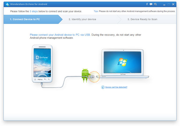
Step 1. Connect your Samsung mobile phone to the computer (enable USB debugging)
Download, install and run Android Data Recovery on your computer, and you'll get the main window below.
- See more at: http://www.android-recovery-transfer.com/recover-deleted-contacts-from-android-phone.html#sthash.cXZeEMn8.dpuf
ownload, install and run Android Data Recovery on your computer, and you'll get the main window below.
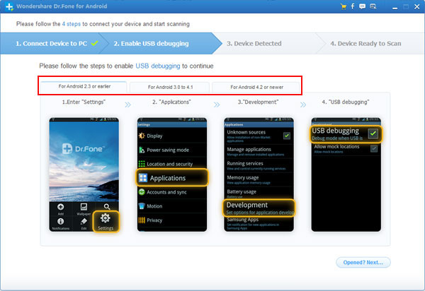
If you didn’t enable USB debugging on your device, you’ll see the
window below. Follow the detailed expression below. There are three
different ways to finish this job for different Android system:
Note: If you have already enabled USB debugging on your device before, you can skip this step.
-
1) For Android 2.3 or earlier: Enter "Settings" < Click "Applications" < Click "Development" < Check "USB debugging"
-
2) For Android 3.0 to 4.1: Enter "Settings" < Click "Developer options" < Check "USB debugging"
-
3) For Android 4.2 or newer: Enter
"Settings" < Click "About Phone" < Tap "Build number" for several
times until getting a note "You are under developer mode" < Back to
"Settings" < Click "Developer options" < Check "USB debugging"
Then connect your Android device to the computer and move to the next step.
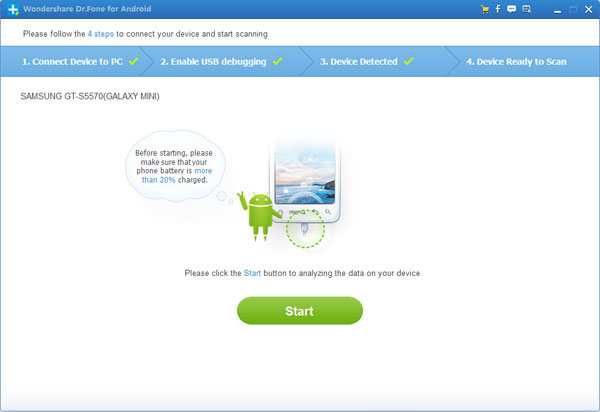
Step 2. Analyze and scan your Android device for lost contacts
After the program detected your Android device, you'll get a window
below. Before scanning your device, let the program analyze it by
clicking “
Start” button.
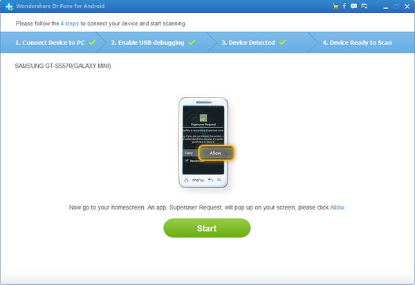
The analysis will take you a few seconds. After that, you'll get a window as follows. As the window shows, click "
Allow" button on your Android device's screen to permit the Superuser Request. Then click "
Start" button on the program's window to begin the scan.
Step3. Preview and restore contacts from Android phones
After the scan, it will remind you when all contacts and messages have
been scanned out. Then you can stop it and preview all your contacts.
Mark the data those you want to get back and click "
Recover" button to save them on your computer.
- See more at: http://www.android-recovery-transfer.com/recover-deleted-contacts-from-android-phone.html#sthash.cXZeEMn8.dpuf
ownload, install and run Android Data Recovery on your computer, and you'll get the main window below.
If you didn’t enable USB debugging on your device, you’ll see the
window below. Follow the detailed expression below. There are three
different ways to finish this job for different Android system:
Note: If you have already enabled USB debugging on your device before, you can skip this step.
-
1) For Android 2.3 or earlier: Enter "Settings" < Click "Applications" < Click "Development" < Check "USB debugging"
-
2) For Android 3.0 to 4.1: Enter "Settings" < Click "Developer options" < Check "USB debugging"
-
3) For Android 4.2 or newer: Enter
"Settings" < Click "About Phone" < Tap "Build number" for several
times until getting a note "You are under developer mode" < Back to
"Settings" < Click "Developer options" < Check "USB debugging"
Then connect your Android device to the computer and move to the next step.
Step 2. Analyze and scan your Android device for lost contacts
After the program detected your Android device, you'll get a window
below. Before scanning your device, let the program analyze it by
clicking “
Start” button.
The analysis will take you a few seconds. After that, you'll get a window as follows. As the window shows, click "
Allow" button on your Android device's screen to permit the Superuser Request. Then click "
Start" button on the program's window to begin the scan.
Step3. Preview and restore contacts from Android phones
After the scan, it will remind you when all contacts and messages have
been scanned out. Then you can stop it and preview all your contacts.
Mark the data those you want to get back and click "
Recover" button to save them on your computer.
- See more at: http://www.android-recovery-transfer.com/recover-deleted-contacts-from-android-phone.html#sthash.cXZeEMn8.dpuf
Step 1. Connect your Samsung mobile phone to the computer (enable USB debugging)
Download, install and run Android Data Recovery on your computer, and you'll get the main window below.
- See more at: http://www.android-recovery-transfer.com/recover-deleted-contacts-from-android-phone.html#sthash.cXZeEMn8.dpuf