Powered by Blogger.
Showing posts with label electronics. Show all posts

Thursday 28 August 2014

The Suitable Solution for Direct10 Kilo Volts Supply


      If you have an application, where you work with kilo volts and you need a suitable diode, we have a solution for you.

It´s not a quite common thing, to find a diode with a reverse voltage of more than 1000V in your “home-drawer stock”. But you develop a device, requiring a diode with a substantially higher reverse voltage and nothing suitable is by a hand …
The help is simple - use the DD1000 diode or in case of higher currents, choose a suitable type from the portfolio of High-voltage types from Diotec and send us your requirement. DD1000 features VRRM up to 10 000V, but in respect to its small dimensions and a construction, it´s suitable only for currents up to 20mA. This is sufficient for construction of various testers, voltage multipliers and similar. Should you require higher currents, many suitable types are available, which still maintain compact dimensions. For more powerful designs, it´s possible to use for example a cylinder type SI-A with a screw connection allowing for simple series connection.


Read more...

Friday 22 August 2014

Maxwells inductance bridge solution and equation evaluation

     The bridge circuit is used for medium inductance and can be arranged to yield results of considerable precision. As shown in figure 1, in the two arms, there are two pure resistances so that for balance relations, the phase balance depends on the remaining two arms. If a coil of unknown impedance Z1 is placed in one arm, then its positive phase angle ɸ1 can be compensated for in either of the following two ways:
  1. A known impedance with an equal positive phase angle may be used in either of the adjacent arms (so that ɸ1 = ɸ2 or ɸ1 = ɸ4), remaining two arms have zero phase angles (being pure resistances). Such a network is known as Maxwell’s a.c. bridge or L1/L4 bridge.
  2. Or an impedance with an equal negative phase angle (i.e. capacitance) may be used in opposite arm (so that ɸ1 + ɸ3 = 0). Such a network is known as Maxwell-Wien bridge or Maxwell’s L/C bridge.
Hence, we conclude that inductive impedance may be measured in terms of another inductive impedance (of equal time constant) in either adjacent arm (Maxwell Bridge) or the unknown inductive impedance may be measured in terms of a combination of resistance and capacitance (of equal time constant) in the opposite arm (Maxwell-Wien bridge). It is important, however, that in each case the time constants of the two impedance must be matched.As shown in figure 1.

Z1 = R1 + jX1 = R1 + jωL1…….unknown;

Z4 = R4 + jX4 = R4 + jωL4….…known;

R2,R4 = known pure resistances; D = detector
The inductance L4 is a variable self-inductance of constant resistance, its inductance being of the same order as L1. The bridge is balanced by varying L4 and one of the resistance R2 or R3. Alternatively, R2 and R3 can be kept constant and the resistance of one of the other two arms can be varied by connecting an additional resistance in that arm.
The balance condition is that Z1Z3 = Z2Z4
(R1 + jωL1)R3 = (R4 + jωL4)R2
Equation the real and imaginary parts on both sides, we have

Z1 = R1 + jX1 = R1 + jωL1…….unknown;
Z4 = R4 + jX4 = R4 + jωL4….…known;
R2,R4 = known pure resistances; D = detector
The inductance L4 is a variable self-inductance of constant resistance, its inductance being of the same order as L1. The bridge is balanced by varying L4 and one of the resistance R2 or R3. Alternatively, R2 and R3 can be kept constant and the resistance of one of the other two arms can be varied by connecting an additional resistance in that arm.
The balance condition is that Z1Z3 = Z2Z4
(R1 + jωL1)R3 = (R4 + jωL4)R2

Read more...

Wheatstone bridge ac circuit explanation and equation solution


     Resistance can be measured by direct-current Wheatstone bridge having resistance in each arm. Inductance and capacitance can also be measured by a similar four-arm bridge, but instead or using a source of direct current alternating current is employed and galvanometer is replaced by a vibrating galvanometer (for commercial frequencies or by telephone detector if frequencies are higher 500 to 2000 Hz.). The general form of an ac bridge arms Z1, Z2, Z3 and Z4 are indicated as unspecified impedances and the detector is represented by headphones. During the balance condition in this ac bridge is reached when the detector response is zero or indicated a null. The condition for bridge balance requires the potential difference from A to C to zero.


At balance con condition,
EBA = EBC or I1Z1 = I2Z2 ———————–(i)
I1 = E/(Z1 + Z4), I2 = E/(Z2 + Z3)—————–(ii)
From equation (i) and (ii)
(Z1E)/(Z1+Z4) = (Z2E)/(Z2+Z3)
Or, Z1Z3 = Z2Z4——————————-(iii)

      Equation (iii) states that the product of impedances of one pair of opposite arms must equal the product of impedance of the other pair of opposite arms.
If the impedance are expressed in complex notation, i.e

.                                                              Z = Z<θ

Or, (Z1< θ1)(Z3< θ1) = (Z2< θ2)(Z4< θ4)

Z1Z3< θ1+ θ3 = Z2Z4< θ2 + θ4 ——————————-(iv)

From equation (iv), we can also write,

Z1Z3 = Z2Z4

The products of the magnitudes of the opposite arms must be equal.
1 + <θ3 = <θ2 + <θ4
The sum of the phase angles of the opposite arms must be equal.

Read more...

Tips to improve or boost your android phone and smart phone battery life

 Today's Android phones pack big bright screens and high-end features that suck plenty of power; here's how to squeeze the most juice out of your battery. 

Top-notch Android smartphones like the Samsung Galaxy  at Amazon and HTC One (M8) are powerful, but unfortunately, they don't have endless battery life. In fact, many Android phone users would be happy to make it through a single day, hoping that a nightly recharge is sufficient.

     Sadly, it sometimes isn't. A number of factors have conspired to reduce gadget endurance over the past several years. Thinner designs with less room for batteries, larger and brighter screens, faster quad-core processors, more software that runs in the background, and power-hungry GPS radios all share responsibility. The move from 3G to 4G networks a few years ago—particularly of the LTE variety—has also taken its toll.

   But there's much more to poor battery life results than that. Fortunately, there's plenty you can do to stem the flow of juice from your Android device. To write this article, I used a Google Nexus 5, as it's running the latest version of Android 4.4 KitKat with no extra interface enhancements, but these tips should apply across just about any Android phone. Try these tips to extend your handset's battery life:

   See what's sucking the most juice. Navigate to Settings > Battery to see an organized breakdown of what's consuming your phone's battery. Applications and features will display in a descending list of battery hogs. If you see an application you barely use or a feature you never use, you'll want to uninstall the app or turn off the feature.


Android Battery Tips


Read more...

Wednesday 20 August 2014

Free Electronics Mini Project Circuits on technology blog

              Here we have presented a list of various mini electronics projects circuits that are published on this blog. This is page is more helpful for the visitors in getting an idea about the different electronics circuits that are present in this blog. You may click on any of the following list of projects to get detailed explanation about that particular project and its circuit diagram.

Read more...

Tuesday 5 August 2014

Bi-Colured LED Blinking Circuit and Dancing circuit or flashing circuit Make it Easy

    LED (Light Emitting Diode) is a semiconductor light emitting diode. We know that diode allows the current in one direction and does not allow the reverse current which will affect the components in the circuit. LED also do the same function but will emit a small light when it allowed the current, which will give the sign or visual indication to the normal human that circuit is working. There are lots of applications using LEDs. They are mainly used for visual indication in any electronic devices, measuring and interacting with the process, displaying the pictures in TV or in any advertisement hoarding, etc.

Two LED blinking circuits are given below. First one is dancing bi-color LEDs (two different color LEDs) where the two color LED will run in sequence. In the second circuit, we will blink the LEDs in regular period of time.

Dancing Bi – Color LED Circuit:

Generally we use small voltage bulbs in the dancing bulbs. This circuit is mainly used in the occasions, decoration articles or in visual indication sign boards etc. In this project, we use bi-color LEDs for sequential running light.

Block Diagram of Bi-Color LED Circuit:

Block Diagram of Dancing Bi-color LEDs
Timer is used for setting the sequential flow rate for the bi-color LED panel. The CD4017 is a decade counter which provides the timing and will make the LED ON/OFF according to the time determined.
Main Components in this Circuit:
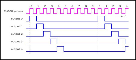
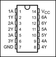
CD4017: CD4017 is a 16 pin decade counter and only 10 pins are used for output. The 4017 will get triggered by the clock pulses. Main operation of the decade counter is as follows: When a clock pulse is taken as an input, only one output is made high for first clock pulse and remaining all output pins will be made low. For the second clock pulse, another output pin is made high and remaining all pins are made low and so on. Time period of the output pin is high according to the width of the pulse. CD4017 is used in many applications where counter is needed.
CD4017 clock pulses from output pins timing diagram is shown below:
CD4017 Clock pulses from output pins timing diagram

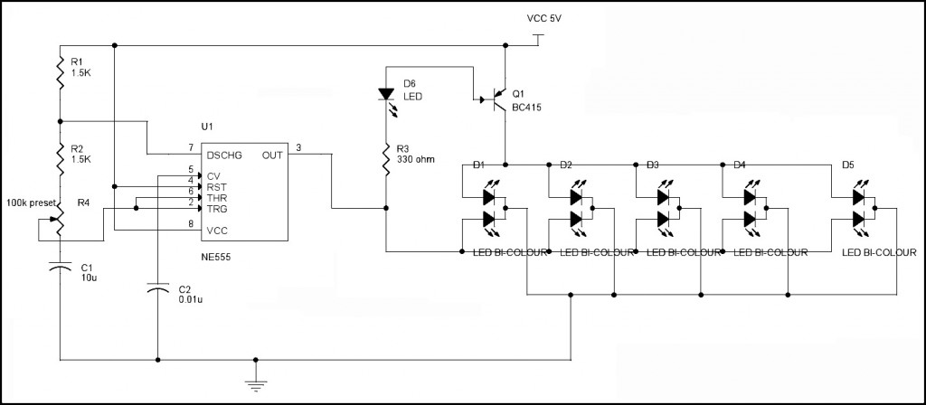
Bi-Color LED Dancing Lights Circuit Diagram:

Dancing LEDs Circuit Diagram
Circuit Diagram Explanation:
  • In the Bi-color LED, it should be connected to the counter as shown in the circuit. The anode of first LED in bicolor LED is connected to the anode of second LED of 10th bicolor LED and in the same fashion, the remaining LEDs are connected, only the second anode of first bicolor LED is connected to the reset pin of the CD4017. All the cathode of bicolor LEDs is made ground.
  • The main operation of this circuit depends on the 555 timer which is set in astable multivibrator mode and decade counter CD4017; the 555 timer will generate low frequency clock pulse and give input to the decade counter which will make the sequential running of the LEDs.
  • Variable resistor can vary the resistance which will change width of the pulse. If pulse width is changed, the time period of running the LEDs will also get changed. We run the LEDs in fast or slow. Running speed can be altered by variable resistor. The first anode of 10th bicolor LED is made short to the reset pin of the decode counter for continuous running of lights.

LED Flasher Circuit:

LED Flasher is a simple circuit which will blink the LEDs in regular time period. This circuit can be used for decoration purpose or can be used for a signaling purpose and many more.

Block Diagram of LED Flasher Circuit:

LED Flasher Block Diagram
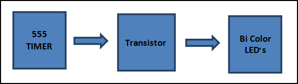
The 555 timer is used to generate the PWM signal which will cause the LEDs to blink. The speed of the blinking by LED is determined by the potentiometer connected to the 555 timer. The PNP transistor is used to flash or blinks the LEDs.

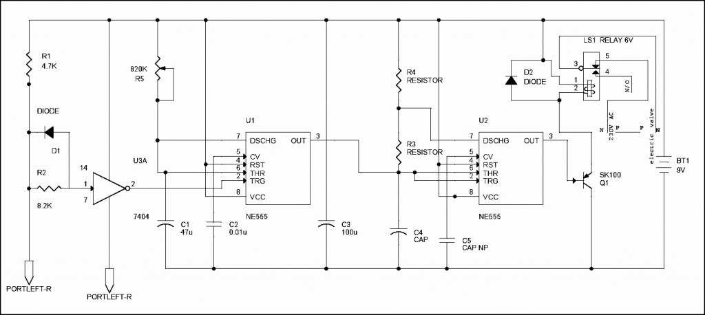
LED Flasher Circuit Diagram:

LED Flasher Circuit Diagram
Circuit Explanation:
  • The 555 timer is made to be configured as a astable multivibrator. The potentiometer which is connected to the timer should be preset and also to adjust the blinking or flashing speed of the LEDs.
  • The bicolor LEDs are used in this circuit and connected to each other as shown in the schematic. The PWM signal is the output of the 555 timer given to transistor, which acts as an inverter. When the pulse generated by 555 timers is low, transistor will get ON and LEDs will get ON. When the input of transistor is high, transistor will get OFF and LEDs are made OFF. This ON/OFF of LEDs will go for every pulse width signal cycle. This mechanism will make the LEDs flashing.

LED Blinking Circuits Applications:

  • Dancing LED circuit can be used for any visual sign indication in any highways or it can be used in advertisement hoarding also.
  • LED blinking circuit can be used in signaling purpose (It can be used as signal for help, if you are in danger)
  • LED blinking circuit can be used as flashing beacon.
  • LED blinking circuit can be used as vehicle indicator when it is broke down in the middle of the road. It can be used in operation theaters or offices as an indication that you are engaged in work.
  • There are lots of applications with these two circuits.

Read more...

AUTOMATIC PLANT IRRIGATION SYSTEM USING IC 555 TIMER

AUTOMATIC PLANT IRRIGATION SYSTEM USING IC 555 TIMER

Here is a simple project more useful in watering plants automatically without any human interference. We may call it as Automatic plant irrigation system. We know that people do not pour the water on to the plants in their gardens when they go to vacation or often forget to water plants. As a result, there is a chance to get the plants damaged. This project is an excellent solution for such kind of problems.

Block Diagram of Automatic Plant Irrigation System:

Block Diagram of Electronic Plant Watering System
Explanation:
  • Circuit is not that much complicated. We use the basic concept in this circuit i.e. soil have high resistance when it is dry and has very low resistance when it is wet.
  • By using this concept we will make the system work. We insert two probes in the soil in such a way that that they will conduct when the soil is wet and they will not conduct when the soil is dry. So, when the probes do not conduct, system will automatically detect this condition with the help of HEX inverter which will become high when the input is low.
  • HEX inverter will trigger the NE555 Timer and this NE555 timer will trigger another NE555 which is connected to the output of first NE555. Now the second NE555 which is configured as astable multivibrator will help to switch on the Electric valve and as result, it will allow the water to flow to the soil.
  • When the water wet the soil, probes will again conduct and make the output of 7404 low which will make the first NE555 to low and also drive remaining circuit to low. So, automatically it will switch off the valve.
Main Components in Automatic Plant Irrigation System:
Hex Inverter 7404: the main function of the inverter is to give the complemented output for its input i.e. it will give output which is opposite to input. For example, if the input is low to the inverter, then the output will be high. Just like the normal inverter which gives high output when the input is low and gives low output when the input is high. 7404 IC will be having six independent inverters; Operating supply voltage is around 4.75V minimum to 5.5V maximum, normal supply voltage is 5V. They are used in different applications like inverting buffers, drivers, hex inverters etc. 7404 IC will be available in different packages like DIP (dual inline package), QFP (Quad Flat Package) etc. The pin configuration of Hex Inverter 7404 is shown below.
Inverter Pin Configuration

Circuit Diagram of Automatic Plant Irrigation System:

Circuit Diagram of Electronic Watering Plant System
Circuit Explanation:
  • We are all well aware that the plants will die due to lack of water in the soil. Soil will have high resistance when it is dry and it will have very low resistance when soil is wet. We use this simple logic to water the plants and make the circuit work.
  • Two probes which are connected to the circuit are placed into the soil. The two probes will conduct only when soil is wet (resistance is low) and they cannot conduct when soil is dry due to high resistance. The voltage is given to the probes to conduct is given from the battery connected to the circuit.
  • When the soil is dry it will produce large voltage drop due to high resistance. This is sensed by 7404 hex inverter and makes the first NE555 timer trigger which is configured as monostable multivibrator with the help of a electrical signal.
  • When the first NE555 is triggered at pin 2, it will generate the output at pin 3 which is given to the input of second NE555 timer. The second 555 timer is configured as astable multivibrator which got triggered by the first 555 timer and will generate the output and drive the relay which is connected to the electrically operated value through the transistor SK100. You can use a heat sink for SK100 transistor if it is dissipating more heat.
  • The output of second NE555 timer will switch on the transistor SK100 which will drive the relay. Relay which is connected to the input of electrical value and output of value is given to the plant plots through the pipe.
  • When transistor has turned on relay, it will open the valve and water is poured on to the plants pot. When the water content in the soil is increased, the resistance in the soil will get decreased and conduction of the probes will get started which will make the 7404 Inverter to stop the triggering of first 555 timer. Ultimately it will stop the electrical valve which is connected to the relay. Variable resistor (R5) and capacitor (C1) are used to adjust the valve when to we want to conduct the probes.
  • The capacitor C5 (0.01uf) is used to ground, the CV pin of second NE555 timer. C3 will remove the AC noise and allow only DC to the remaining circuit. C4 and R3 will constitute to configure the NE555 in astable multivibrator.
Values of the Components in the Circuit:
  • Capacitor (C4) = 10u 16V.
  • Capacitor (C5) = 0.01u.
  • Resistor (R3) = 27K
  • Resistor (R4) = 27K
  • Diode (D1 and D2) = IN4148
  • Relay = 6V, 150 ohms
Note:
  • Battery should be continuously monitored from power outage or simply you can use 9V DC supply adaptor.
  • Probes must be inserted into the soil. They should not be kept on the soil.
  • Electric valve should be used for best result.

Read more...

water level indicator and controller using 8051 micro controller

This article explains you how to detect and control the water level in an overhead tank or any other container. This system monitors the water level of the tank and automatically switches ON the motor when ever tank is empty. The motor is switched OFF when the overhead tank or container is FULL. Here the water level of the tank is indicated on LCD (Liquid crystal Display). Using this system, we can avoid the overflow of the water. We have already seen How water level indicator circuit works using AVR Microcontroller in the earlier post. But, here we are designing the circuit which is used to detect and control the water level automatically in overhead tank using 8051 microcontroller.
In this system water sensing can be done by using a set of 4 wires which are placed at different levels in tank. DC supply probe is placed at the base of the tank.

Water Level Controller using 8051 Circuit Principle:

This system mainly works on a principle that “water conducts electricity”. The four wires which are dipped into the tank will indicate the different water levels. Based on the outputs of these wires, microcontroller displays water level on LCD as well as controls the motor.

Circuit Diagram:

Circuit Diagram of Water Level Controller using 8051 Microcontroller
Circuit Components:
  • At89c51 controller
  • At89c51 programming board.
  • 16*2 LCD
  • 5V Relay
  • Bc547 (NPN) transistors – 5
  • Resistors (1K) – 4
  • Resistor – 330 ohm
  • AC Motor
  • Pot – 10k
  • Programming cable
  • Connecting wires

Water Level Controller using 8051 Circuit Design:

The main heart of this project is AT89C51 microcontroller. The water level probes are connected to the P3.0, P3.1, P3.2, and P3.3 through the transistors. Port P2 connected to the data pins of LCD and control pins RS, RW and EN of LCD are connected to the P1.0, P1.1, and P1.2 respectively.
Initially when tank is empty, LCD will display the message EMPTY and motor runs automatically. When water level reaches to quarter level, now LCD displays QUARTER and still motor runs. For further levels, LCD displays the messages HALF and ¾ FULL.
When tank is full, LCD displays FULL and motor automatically stops. Again motor runs when tank is empty.


Algorithm for Water Level Controller Circuit:

  • First configure the controller pins P3.0, P3.1, P3.2 and P3.3 as inputs and P3.4 as output.
  • Now initialize the LCD.
  • Continuously check the water level input pins P3.0, P3.1, P3.2, and P3.3
  • If all the pins are low then display tank is empty on LCD and make P3.4 pin high to run the motor automatically.
  • High pulse on the pin P3.0 indicates quarter level, display the same thing on LCD.
  • If P3.1 is high then water level is half.
  • High pulse on P3.2 indicates 3/4th full of the tank.
  • If P3.3 is high then tank is full, now make P3.4 pin is low to turn off the motor automatically.

How to Operate Water Level Controller Circuit using 8051 Microcontroller?

  1. Initially burn the program to the controller.
  2. Now give the connections as per the circuit diagram.
  3. While giving the connections, make sure that there is no common connection between AC and DC supplies.
  4. Place the 4 water level indicating wires into the small tank.
  5. Switch on the supply, now the motor will run automatically as there is no water in the tank.
  6. Now pour the water, when it reaches to quarter level then LCD displays QUARTER on LCD.
  7. For further levels it will displays HALF and ¾ FULL on LCD.
  8. Still if you pour the water then LCD displays FULL and motor turns off automatically when the tank is full.

Water Level Controller Circuit Advantages:

  • Human effort is reduced as the system controls the motor automatically based on the water level.
  • This system consumes less power.
  • Simple and more reliable.

Applications of Water Level Controller Circuit using 8051:

  • Used in big buildings where the manual monitoring is difficult.
  • Used in industries to control the liquid level automatically.

Read more...

Sunday 17 November 2013

Laptop-keyboard-repair-solutions how to repair laptop keyboard


Steps:  
    replace-keyboard-palmrest_sh.jpg
It works hard, plays hard, and goes everywhere with you. But with all that use, certain laptop parts can wear out. Even systems that still run perfectly well on the inside may suffer from problems on the outside. The most visible signs of aging and abuse are often found on the keyboard; keys may have stopped working after one or two accidentally spilled beverages, or cosmetic flaws, such as rubbed out letters, may have started to appear. But you don't need to replace your entire laptop, just the keyboard.
To find the right keyboard for your system, start by checking with the laptop manufacturer to see if they sell replacements. If not, spare part dealers, can help. This site has an online tool for locating parts. Simply enter the manufacturer, model line, series, and model number of your notebook. (eBay is another good source for new or used parts.) We found a keyboard for our aging Lenovo ThinkPad Z61t for $60.
Depending on the model and age of your laptop, a replacement can cost as little as $20 or as much as $130. Prices vary, so shop around for the best deal. Research a seller's history carefully, and check the return policy before you complete your purchase.
Once you have the replacement keyboard, swapping it for your old one will be easy. The entire process should take only 15 to 20 minutes.
  1. Replacement keyboard for your specific laptop model
  2. Phillips-head screwdriver
  3. Tray for keeping loose screws

Read more...
Related Posts Plugin for WordPress, Blogger...

Random Posts

Recent Comments

Total Pageviews

Search This Blog

About Template

Digital Solutions - Technology Blog

  © Blogger templates ProBlogger Template by Ourblogtemplates.com 2008

Back to TOP